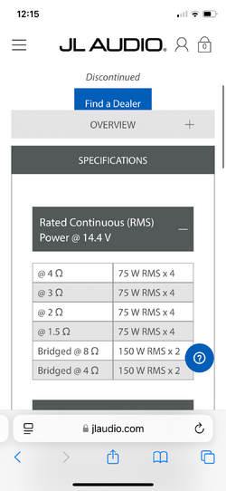
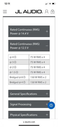
Hello, I am currently using a 6.5 inch JL audio C-5 component set in the front of my car. The woofers in the doors and the tweeters in the corners of the dash. I am powering them with a JL audio slash 300v3/4 4channel amplifier. this amp will supply 75 W to each speaker regardless of voltage or ohm load it gets (R.I.P.S) technology
My car is a Kia soul, it did not come with the centre speaker. However, I put in a 6.5 inch JL audio VR component woofer there. I am sending the audio signal to the centre speaker using the positive + from the left crossover woofer output and the negative - from the right crossover woofer output. My question is: what is the ohm load that my amp is seeing? All of the woofers are for rated for 75 watts/4 ohm . I was also wondering if it’s taking away power from the woofers in the doors.
Any advice would be appreciated. Thanks, Jon