Umbra
Hobbyist & CA Tenderfoot
.
Hate reading? Look at the pictures and tell me if those spots work for the Big 3.
.
I tried to do the Big 3 Upgrade today, but got nowhere near physically completing it. I did plan out the locations though. I was all set to work into the night under a single hanging lamp, but I figured I be a courteous neighbor and not hammer and drill as people are trying to get to sleep. I read some articles and watched some videos, but none of them covered my exact model. Moreover, I've never spent any real time under the hood and everything's covered in residue, so I'd like to take this time to double check the termination points with you guys before I start a fire.
You can click on the images to make them bigger.
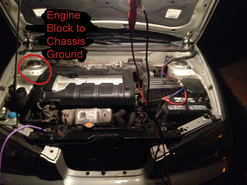
Firstly, here's an overview of the engine bay so you can see where things are in relation to each other. The alt is on the bottom left and a little in (though it can't be seen from this angle) and the battery is on the bottom right. I watched a video that suggested the strut towers make for good grounds to the chassis, so I figured the left one can be fore the engine block to chassis and the right one can be for battery negative to chassis.
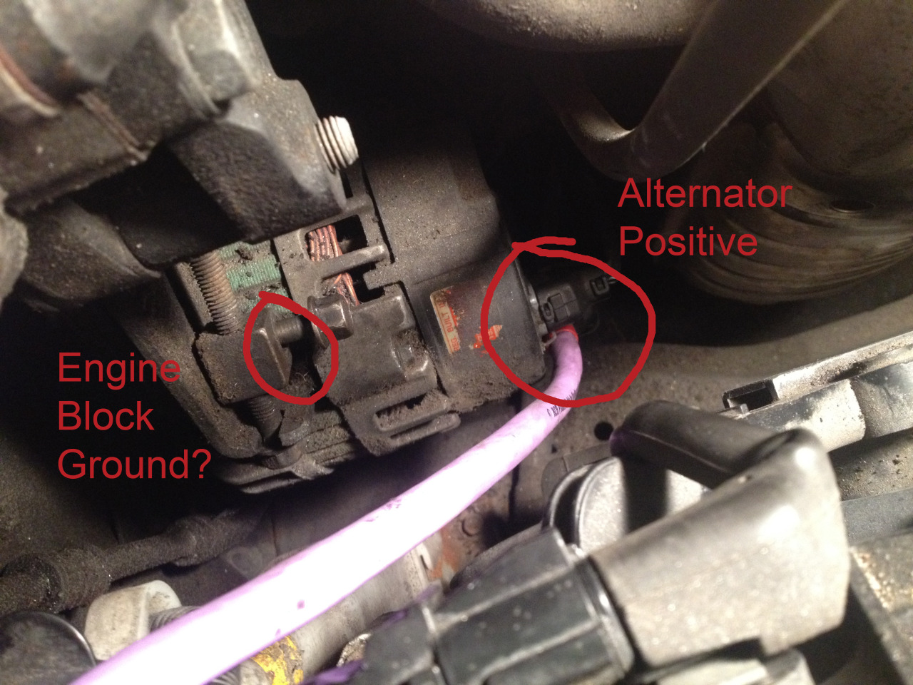
This is a top-down shot of the alternator. It took me awhile to figure out where the positive bolt was, but I think I found it. Next to the plastic-covered wiring harness (below in this picture) there is another plastic cover. If you pop that off there's a relatively thick wire terminated on a bolt. I began an additional run of 4 gauge wire here. Now the point that really threw me is the engine block ground. Another video I watched told me the alternator housing is grounded through the engine block, so by that logic if I can bolt it to the alt housing that'd be close. In the picture, I'd already taken it off and then put it back partially. I'll clean it up tomorrow if it's a good spot. The horizontal bolt goes through that block and the big piece of metal to the left. The vertical bolt just goes through the block and goes into that notch at the bottom. I think it's for extra support.

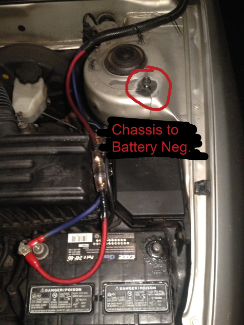
The last picture is just a shot of the strut tower. I ground off the paint for a good connection. If this is a suitable chassis ground I'd like to repeat the process on the passenger side for the engine block to chassis connection.
If there's any more details I can give to help you help me, let me know.
Thanks for looking.
Hate reading? Look at the pictures and tell me if those spots work for the Big 3.
.
I tried to do the Big 3 Upgrade today, but got nowhere near physically completing it. I did plan out the locations though. I was all set to work into the night under a single hanging lamp, but I figured I be a courteous neighbor and not hammer and drill as people are trying to get to sleep. I read some articles and watched some videos, but none of them covered my exact model. Moreover, I've never spent any real time under the hood and everything's covered in residue, so I'd like to take this time to double check the termination points with you guys before I start a fire.
You can click on the images to make them bigger.
Firstly, here's an overview of the engine bay so you can see where things are in relation to each other. The alt is on the bottom left and a little in (though it can't be seen from this angle) and the battery is on the bottom right. I watched a video that suggested the strut towers make for good grounds to the chassis, so I figured the left one can be fore the engine block to chassis and the right one can be for battery negative to chassis.

This is a top-down shot of the alternator. It took me awhile to figure out where the positive bolt was, but I think I found it. Next to the plastic-covered wiring harness (below in this picture) there is another plastic cover. If you pop that off there's a relatively thick wire terminated on a bolt. I began an additional run of 4 gauge wire here. Now the point that really threw me is the engine block ground. Another video I watched told me the alternator housing is grounded through the engine block, so by that logic if I can bolt it to the alt housing that'd be close. In the picture, I'd already taken it off and then put it back partially. I'll clean it up tomorrow if it's a good spot. The horizontal bolt goes through that block and the big piece of metal to the left. The vertical bolt just goes through the block and goes into that notch at the bottom. I think it's for extra support.
The last picture is just a shot of the strut tower. I ground off the paint for a good connection. If this is a suitable chassis ground I'd like to repeat the process on the passenger side for the engine block to chassis connection.

If there's any more details I can give to help you help me, let me know.
Thanks for looking.
Last edited by a moderator:


