Solder vs crimp.

I have both done in with my build.

Neither of which have failed or came off on me yet.

It will fail is if you don't solder it correctly. You have the let the solder "soak in" with the wire and the lug and then cap it.

There is a possibility of the solder melting because of the heat of the wire.

Cost is also a factor, depending on the crimper you get, it could be a lot cheaper to a map gas torch and some solder.

Some of those crimpers are expensive.

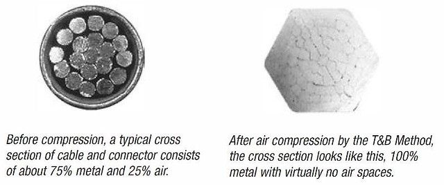
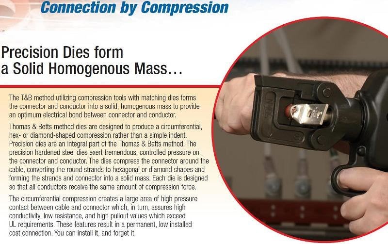
If you crimp you're doing a direct connection with the wire and the lug.

Crimping is 100 times easier to do than soldering.

Picked up one of those yellow 20 ton hydraulic crimpers. I think it was on ebay for under $30.

Works great and thats all I use now.

This is specifically going for larger gauge wire. All the small wire connections I have to do are soldered (10 gauge and up)

 
Ive always used a hammer and the concrete floor..Then take a punch and make three indentions on both sides and use heat shrink for a final finish.I have never had any wiring come loose and Always had a hell of a sturdy connection.Never an issue coming apart

 
I actually machined something from some aluminum I have stashed in my garage. Made a "V" block, to rest the lugs onto and another piece of aluminum with chamfered sides to hammer down the lugs. So far isn't a bad idea really.

 
EXO made a vid on Youtube long time ago about this and he used a manual hammer type crimper.....even showed himself hanging onto the wire while crimped side hanging on a big pillar!

 
For mine, the main radio plug was mated to the Metra 70-1817 Receiver Wiring Harness. The splices are staggered by about 1", in three groups, so that all the splices DO NOT happen at the same position. I use soldered Western Union splices, covered w/ adhesive-lined heat shrink tubing. (Never apply too much solder that wicks up under the insulation, making the wire stiff.) All of the wires are labeled for function. I use my Brady IDxpert, in these cases printing on shrink tubing or on adhesive self-laminating label stock.

36760378901_50d3668e21_b.jpg


36091846503_a1ae487b4b_b.jpg


36760379101_0773e98177_b.jpg


36760379051_bab38802b2_b.jpg


36091846753_d993e6f69b_b.jpg


36760379171_5be1e2cb91_b.jpg


The objective for a proper crimp is to use the connector barrel and the crimp tool to deform / reshape the parts from individual conductor strands surrounded by air to a homogenous mass, devoid of air, as-shown in these images.

36945968053_1e23958a89_z.jpg


23761418498_08fda6f461_b.jpg


My experience w/ the hammer tool is that it has not provided acceptable results, so I've discontinued usage and instead use high-quality crimp tools.

All of the finished crimp images from those inexpensive hydraulic tools that I have seen look horrible. They look like the crimp die sizes are totally wrong and inappropriate for the crimp connectors.

The connector manufacturers have detailed specifications for the crimp to attain acceptable results. The inexpensive tools frequently fail to satisfy the specified crimp requirements.

 
Activity
No one is currently typing a reply...
Old Thread: Please note, there have been no replies in this thread for over 3 years!
Content in this thread may no longer be relevant.
Perhaps it would be better to start a new thread instead.

About this thread

Lbetts818

CarAudio.com Elite
Thread starter
Lbetts818
Joined
Location
Midland mi
Start date
Participants
Who Replied
Replies
29
Views
4,718
Last reply date
Last reply from
wingless
Screenshot_20240424-005730.png

1aespinoza

    Apr 24, 2024
  • 0
  • 0
1000005348.jpg

Deepak Walia

    Apr 23, 2024
  • 0
  • 0

Latest topics

Top