2014 Accord Alarm Remote Start Viper 5706V

  • 1
    Participant count
  • Participant list

keep_hope_alive
Premium Member

Acoustics Engineer
Sharing the wiring instructions for a 2014 Accord, not push to start models.

What i used:

Viper 5706V 2-way with LCD remote.

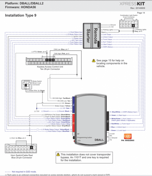
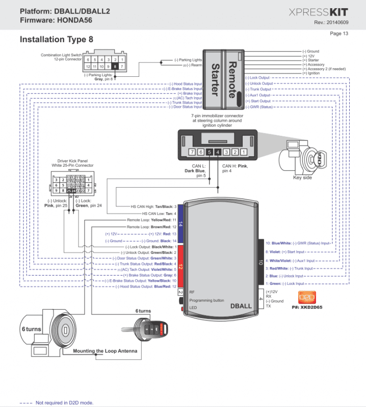
Xpresskit DBALL2 programmed with DBALL2 - 402.HONDA56 2.16

http://www.xpresskit.com/CompatibilityChart.aspx?productid=553&firmwareid=9432&firmwarename=402.HONDA56&firmwareversion=2.16&c=223

This combo handles all models of Accord (smart key or non).

You will need the manual for the DBALL2

http://www.xpresskit.com/DocumentDownload.aspx?documentid=9565&productid=553&firmwareid=9432

The non-PTS models are Install Type 8. Start by comparing the list for the Interface with the list for the Alarm. Note all of the features that a D2D interface will provide for you. The D2D interface communicates via CAN Bus to eliminate most of the wiring connections needed.

All of the connections dashed blue are not needed thanks to D2D. Note that 4-pin harness is the D2D harness to the alarm brain, it handles power, ground, and data.

xpresskitType8.png


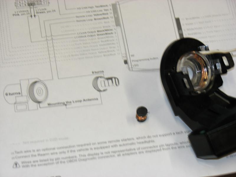
You need to sacrifice your grey valet key (no buttons). You wrap wire around the key and around the cylinder... but that's easier said than done. So i used laminated wire from a small inductor and soldered that to the wiring from the Interface.

attachment.php


I disassembled the key cylinder cover and wrapped the thin wire around the outside of the clear piece. I used thin strips of electrical tape to hold it in place.

attachment.php


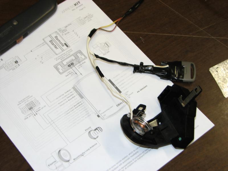
wrap laminated wire around the base of the key (where the RFID chip is)

attachment.php


attachment.php


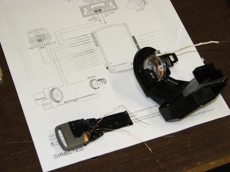
be sure to tape/heatshrink the connections to fully protect them. This photo is for demonstration, i extended the wiring to the key to hide it deeper in the dash.

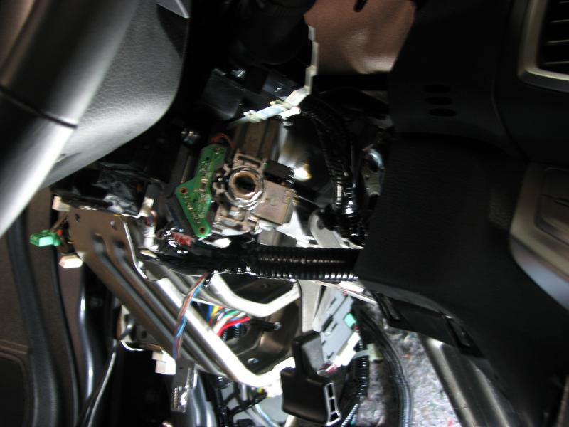
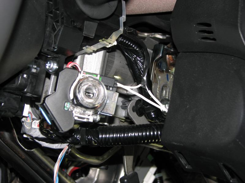
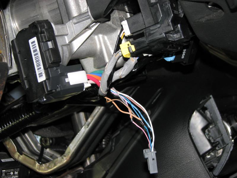
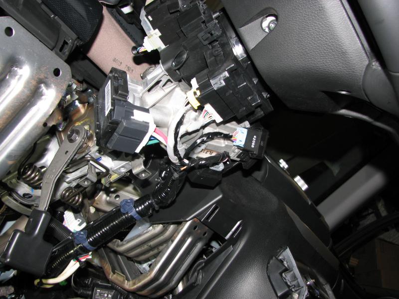
you will notice that the immobilizer housing has an arm with a hole in it - a small Phillips screw is located here, it's not easy to remove. a metal bracket held with two 10mm bolts has the main wiring harness wire clips in it - remove that and you have more access to the screw.

attachment.php


You can intercept CAN Bus wiring at the steering column also. bottom trim is held with one phillips screw in the middle and two phillips screws up top - rotate the steering wheel to gain access to them.

attachment.php


be sure to tape/loom/tie wires up when you're done

attachment.php


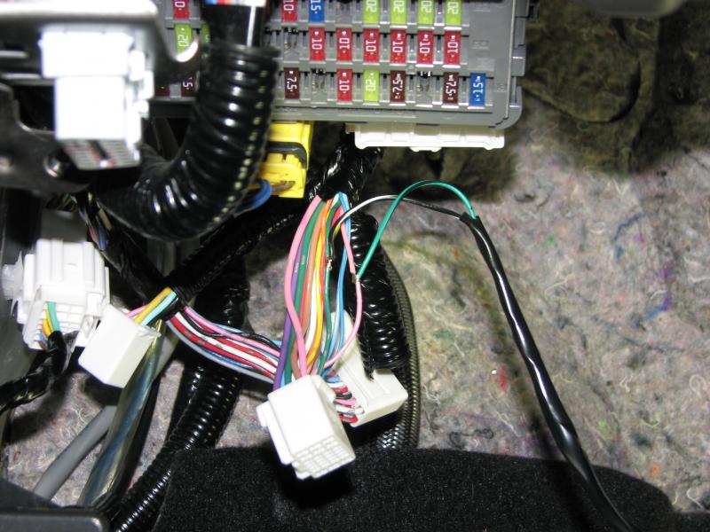
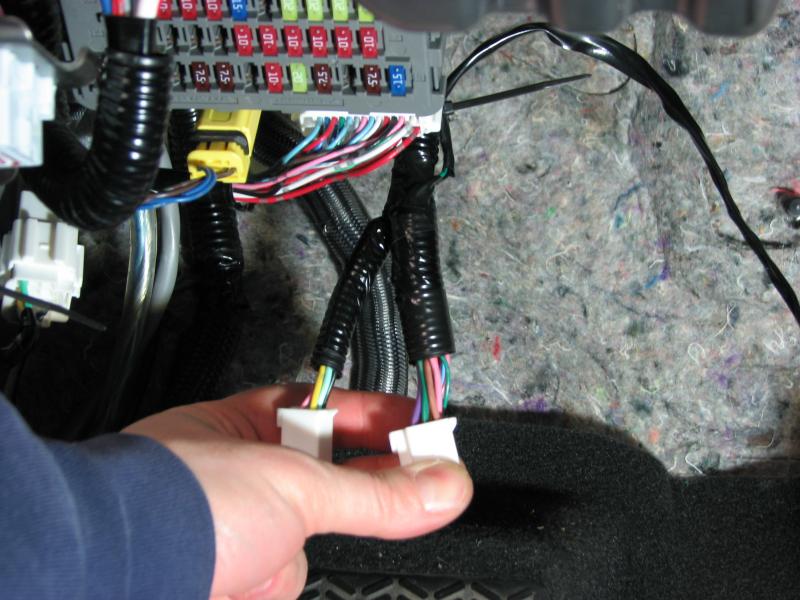
The lock and unlock wiring is also easily accessed in the driver's door harness - it's located where the rubber boot passes wiring to the door.

attachment.php


attachment.php


That completes vehicle wiring for the Xpresskit. Next we wire the 5607V brain.

 
Viper 5706V

Main Harness (6-pin)

1 RED (+12v) constant 12V. White wire in 5-pin heavy gauge harness

2 BLACK (-) Ground to chassis

3 BROWN (+) Siren output - wire to siren in engine bay. (ground siren in engine bay)

4 WHITE/BROWN LIGHT FLASH ISOLATION WIRE - not used

5 WHITE PIN 30 of LIGHT FLASH RELAY - can be + or -. I set to + and intercepted a red wire in large green harness (see pic). - connection is a gray wire at steering column harness.

6 ORANGE 500 mA GROUND WHEN ARMED OUTPUT - I tied this to a Tilt sensor orange wire, otherwise not used.

attachment.php


Door Lock Harness (3-pin)

1 BLUE (-) 500mA UNLOCK OUTPUT - Not used, D2D takes care of this

2 NO WIRE

3 GREEN (-) 500mA LOCK OUTPUT - Not used, D2D takes care of this

Aux/Shutdown/Trigger Harness (24-pin)

1 PINK/WHITE (-) 200mA FLEX RELAY CONTROL OUTPUT Not used

2 BLUE/WHITE (-) 200mA 2ND STATUS /REAR DEFOGGER OUTPUT The rear defroster wire is Brown. Below dash fuse box, white 28 pin plug, pin 11

3 RED/WHITE (-) 200mA TRUNK RELEASE OUTPUT D2D takes care of this

4 BLACK/YELLOW (-) 200mA DOME LIGHT OUTPUT Not used

5 DARK BLUE (-) 200mA STATUS OUTPUT Not used, D2D takes care of this

6 WHITE/BLACK (-) 200mA AUX 3 OUTPUT Not used

7 WHITE/VIOLET (-) 200mA AUX 1 OUTPUT Not used

8 ORANGE/BLACK (-) 200mA AUX 4 OUTPUT Not used

9 GRAY (-) HOOD PIN INPUT (NC OR NO) Not used, D2D takes care of this

10 BLUE (-) TRUNK PIN/INSTANT TRIGGER - I tied this to the Tilt sensor blue wire, not used otherwise, D2D monitors the trunk

11 WHITE/BLUE ACTIVATION INPUT Not used

12 VIOLET/WHITE TACHOMETER INPUT D2D takes care of this

13 BLACK/WHITE (-) NEUTRAL SAFETY INPUT - Ground to Chassis

14 GREEN/BLACK (-) 200mA FACTORY ALARM DISARM OUTPUT D2D takes care of this

15 GREEN (-) DOOR INPUT Not used, D2D takes care of this

16 BROWN/BLACK (-) 200mA HORN HONK OUTPUT - Not used

17 PINK (-) 200mA IGNITION 1 OUTPUT Not used

18 VIOLET (+) DOOR INPUT Not used

19 VIOLET/BLACK (-) 200mA AUX 2 OUTPUT Not used

20 BROWN (+) BRAKE SHUTDOWN INPUT D2D takes care of this

21 VIOLET/YELLOW (-) 200mA STARTER OUTPUT Not used

22 GRAY/BLACK (-) DIESEL WAIT TO START INPUT Not used

23 ORANGE (-) 200mA ACCESSORY OUTPUT Not used

24 GREEN/WHITE (-) 200mA FACTORY ALARM ARM OUTPUT Not used

Remote Start, 10-pin heavy gauge harness

All connections made to green heavy gauge harness below dash or at steering column.

1 No Wire

2 RED/BLACK (+) FUSED 12V ACC/STARTER INPUT - White wire

3 PINK/BLACK (+) FLEX RELAY INPUT - not needed

4 PINK/WHITE (+) IGNITION 2/FLEX RELAY OUTPUT - Red wire **

5 RED (+) FUSED 12V IGN 1 INPUT - White wire

6 GREEN (+) STARTER INPUT (KEY SIDE STARTER KILL) - Blue (to column)***

7 VIOLET (+) STARTER OUTPUT (CAR SIDE STARTER KILL) - Blue (to fuse block)***

8 ORANGE (+) ACC OUTPUT - Orange wire

9 RED/WHITE (+) FUSED 12V IGN 2 INPUT - White wire

10 PINK (+) IGN 1 INPUT/OUTPUT - Green wire

** Program Viper 5607V Menu 3, Item 8 to Option 2 for Flex Relay = Accessory 2.

*** Cut the Blue wire. This is the only wire you need to cut. This is the starter interrupt function.

attachment.php


---------- Post added at 10:05 PM ---------- Previous post was at 10:04 PM ----------


Hopefully this will save some people some time. It wasn't immediately clear if i had to cut the factory blue wiring for starter input/output because the Xpresskit says it handles starter output. I found some info, but nothing specific for the non-PTS models.

I got the 5706V online for around $220. I got the Xpresskit DBALL2 from my local dealer for $80 and they programmed it free of charge.

without the tilt sensor, the only wire i needed to connect in the large 24-pin harness is grounding the black/white wire. I bundled the rest but did save the aux outputs for future use.

Others have said that using the iDataLink interface eliminates the need for wiring a key. I've used iDataLink before with good success. I went with Xpresskit because they are also made by Directed (same as Viper) and I figured the D2D would be more seamless. It appears that the Xpresskit is much easier to program as well. Below are features retained by D2D and the final programming method (4 steps in gray - white is done by dealer).

If you do have a PTS model, the interface wiring is as follows:

xpresskitType9.png


I had an issue where the car would start on RS but then shut off after 20 seconds or so. it would then attempt to restart twice (no fire). then it would give up and just tell me "remote start off" on my key fob. it wasn't all of the time but most of the time. it would also sometimes fail to keep the car running in "pit stop mode".

you can do diagnostics on the last remote start shutdown (refer to install manual) and it told me low voltage (voltage mode).

I did some digging and the solution is in regards to the tach.

I had it programmed for virtual tach. it looks at voltage and expects to seen an increase in voltage. but this car regulates voltage at 12.5VDC when the headlights are off (possible ELD). so the car would start and the voltage would be the same and the 5706V thought the car wasn't running. i'm not sure why it failed to restart.

I reset the virtual tach.

I changed the programming from Virtual Tach to tach.

I performed the tach learning procedure.

The system confirmed it learned the tach through D2D.

car seems to start fine now. all of it makes sense.

 
Activity
No one is currently typing a reply...
Old Thread: Please note, there have been no replies in this thread for over 3 years!
Content in this thread may no longer be relevant.
Perhaps it would be better to start a new thread instead.

Similar threads

I thought you had two amps?? What happened to the wood that you were going to have H.depot cut out?? Looks different to me for some reason. Do you...
9
2K
This is the max fuse sizes for the knu wire. The kca 4awg kit can supply 100amp to the rp1200.1 but it won't have enough left over for the rp75.4...
26
3K
Another option is to get the 4 channel amplifier and purchase 2 surface mount speakers for the rear deck and 2 for the front kick panels. Running...
3
965
I just ordered a Sony XM-GS4 amp for the Focal door speakers. The Mosconi Pico 2 powers the factory subwoofer, and sail panel tweeters. I'll post...
3
659
Did you consider using the PAC AmpPRO 4, AP4-CH31? It will connect between factory amp and head unit and allow you to have RCA outputs for the amps.
5
1K

About this thread

keep_hope_alive

Premium Member
Acoustics Engineer
Thread starter
keep_hope_alive
Joined
Location
Quad Cities, IL
Start date
Participants
Who Replied
Replies
2
Views
4,970
Last reply date
Last reply from
keep_hope_alive
IMG_7545.png

Chris Gerrish

    Apr 25, 2024
  • 0
  • 0
IMG_7544.png

Chris Gerrish

    Apr 25, 2024
  • 0
  • 0

Latest topics

Top