Wiring amp for all speakers with a cutoff switch

  • 4
    Participant count
  • Participant list

mty_550

Junior Member
So I know how to wire a cutoff switch to the amp on the sub alone, but what I want to do is wire a cutoff switch to all the amps but still be able to play music with the amps shut off. Anyone here have the know how to do this? Or is there a good write up on what I am looking for? I have been searching but maybe I'm searching the wrong way...I don't know.

I guess it would be similar to how the audio stores wire up their displays but I don't know how that is done, using relays I'm sure. Can anyone help out? Thanks

 
i've done this before on a boat. we wanted the owner to run off the head unit for low power listening but then be able to engage an external amp for high power listening.

there are two ways to do this. the cheap way is with a collection of DPDT toggle switches. they will have On-Off-On configuration so you can select source 1 (head unit) or source 2 (amp). one for each speaker + remote. cheap but effective and also allows selection of which speakers to keep on (for the boat this worked well).

the better solution is to use 5-pin relays. the N.C. position will be the head unit source. the N.O. position will be the amp. one master toggle switch will control power for the amp remote turn-on and the relay coils. you will need two relays per speaker.

 
to describe in more detail:

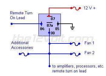
you don't want the head unit remote output to be responsible for all of the current necessary, so you'll start with a relay for remote turn-on.

addremacc.gif


the blue lead (pin 30) in the image above will be +12V power for the amp(s) and relay coils.

you can tie pin 87 to the head unit ignition wire (also red).

now for the speaker relays:

pin 85 and 86 are for the coil.

wire each pin 86 together to the +12V lead. keeping this blue makes sense.

wire each pin 85 together and wire to ground. keeping this black makes sense.

wire each pin 30 to a speaker. since the relays will be in pairs, one 30 goes to speaker (+) and one 30 goes to speaker (-)

wire each pin 87a to the head unit output. similar to above, one relay for (+) and one for (-)

wire each pin 87 to the amplifier output. similar to above, one relay for (+) and one for (-)

use a standard BOSCH style 5-pin relay but make sure it has 87 and 87a contacts. If you get a relay socket it helps with wiring and saves time.

330-079_HR_0.jpg


12 VDC Waterproof 5-Pin Relay SPDT 30/40A with Metal Bracket | 330-079

330-075_HR_0.jpg


12 VDC 5-Pin Relay Socket For Bosch Type Relay | 330-075

 
when wiring this up, it will be difficult to manage wiring. i recommend getting some insulated terminal blocks so you can land wires the relays in an orderly fashion and then have a place to land all of your speaker wires.

 
Just to add to Keeps excellent info the12volt.com has all the diagrams to help out with this type application. I did a similar set up with my cooling fan I wired the NC side to the factory fan control but used the NO side to run controlled by a switch manually due to losing the lowspeed fan sensor.

 
Just to add to Keeps excellent info the12volt.com has all the diagrams to help out with this type application. I did a similar set up with my cooling fan I wired the NC side to the factory fan control but used the NO side to run controlled by a switch manually due to losing the lowspeed fan sensor.
that site has a lot of diagrams, but not what he wants. i know because i've looked before and had to make my own. i didn't save the hand sketch and I don't think it's really necessary.

i did come up with a relay scheme that allowed me to switch from bridged non-biamp to biamp with passive crossovers. i wanted to see if separate level control and T/A would be more beneficial than more power. this would also work for bridging a 4 channel amp to two channels for more power for front and rear speakers but losing fader.

relaybridgingafter008.jpg


speakerbridgingrelays.jpg


this is how the boat system with the toggle switches ended up (same concept as the OP wants)

it had six speakers. he could choose which four of the six he wanted on the head unit or run all six off the amp.

HUandswitches.jpg


RandysBoatInstall005.jpg


owner wanted the amp there, could have been tucked away but it stays cool.

 
Activity
No one is currently typing a reply...
Old Thread: Please note, there have been no replies in this thread for over 3 years!
Content in this thread may no longer be relevant.
Perhaps it would be better to start a new thread instead.

Similar threads

I have a jeep wrangler 2010 4 door.. So 2 of my speakers are in the dash upfront. And the other 2 are in the bar in the middle of the car
6
1K
For clarity, why not example 2 ? Example 2 is 2 ohm...my speakers are 4 ohm and amp uses less RMS wattage with the bridged 4 ohm full range...
3
2K
Wiring question....using four 4 ohm speakers and one 2 channel amp capable of 2.ohm load... Using 2 ohm stable 2 channel 4 ohm amp to power four...
0
1K
I agree with every one above. OFC is much better. Copper is a much better conductor than aluminum.
6
433
In a case like In a case like yours I would rather recommend tactile transducers. They are like woofers without the cone section that are...
7
946

About this thread

mty_550

Junior Member
Thread starter
mty_550
Joined
Location
Beaverton, OR
Start date
Participants
Who Replied
Replies
7
Views
1,769
Last reply date
Last reply from
CrossoverOre
1000008028.jpg

Mr FaceCaser

    May 20, 2024
  • 0
  • 0
1000008027.jpg

Mr FaceCaser

    May 20, 2024
  • 0
  • 0

New threads

Top