- Thread Starter
- #31
This took some time!
Transmission Lines
NOTE: There are typically two types of TL enclosures: ones for us, and ones for others. The ones for us are what you typically see on here and involve output at the exit of the line. The other type is designed such that there is no output at the exit and functions simply to completely eliminate box resonance by fully damping any waves from the rear of the speaker. That models roughly as the ideal sealed enclosure and isn't intended to produce extra bass, but is perhaps the smoothest sounding enclosure you can have. The design theory is the same, although this write up concerns the first type.
Also note that I use terms like tube or pipe. That doesn't mean that a TL is supposed to by a cylinder because it doesn't have to be.
Alright, down to one of the more unique enclosure types out there. It seems like everyone here wants to know about the magical being that is the transmission line. They think that it's something so revolutionary or so technical that there's no way that they'd ever be able to build one, let alone design one themselves. Think again. //content.invisioncic.com/y282845/emoticons/smile.gif.1ebc41e1811405b213edfc4622c41e27.gif
The best way to start this discussion is to talk about a ported box. As I didn't say previously in the ported box section since it wasn't really necessary, a woofer moving on a baffle emits two waves: the front wave and the back wave. Picking whichever reference point you want, the two waves are 100% out of phase with one another. Scientifically, this means that they are 180 degrees out of phase with one another. What is phase? All that phase is is a displacement of a wave from a reference point. What does that mean? Well, lets take a look at a picture, shall we?
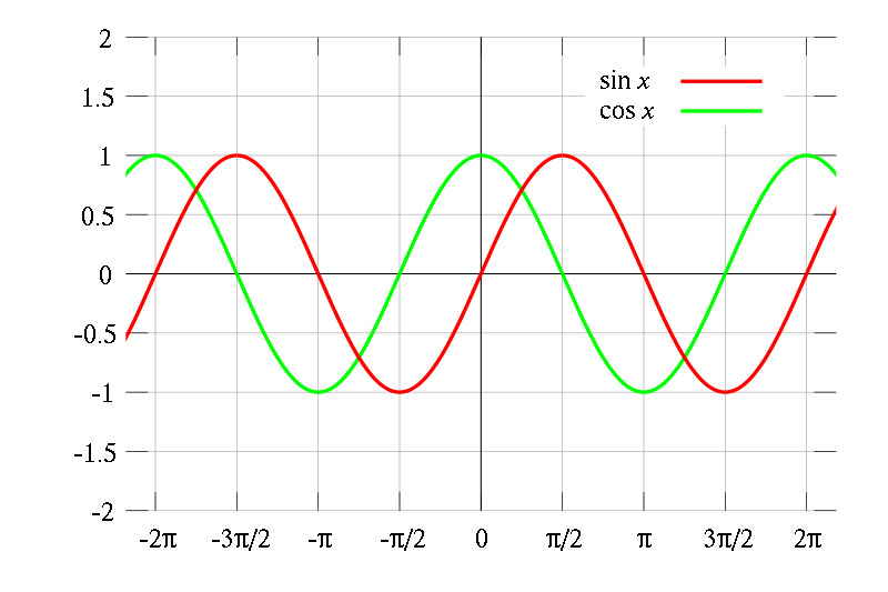
The sine wave and the cosine wave are 90 degrees out of phase with one another. If you've forgotten or never learned, angles in units of "pi" are called radians. 2*pi radians is equal to 360 degrees, so 90 degress is equal to 1/4 of 360, so it's pi/2 radians. Why is that important? Look at 0 radians for the cosine wave, then look at pi/2 radians for the sine wave. What do you see? If you start looking at the sine wave at pi/2, then they're the same wave! Interesting, you might say, but not terribly important. Hold on there, that's the entire point behind transmission lines. Let's look at two waves, which will represent the front and back waves of your speaker:

As you can see, these two waves are 180 degrees out of phase, or pi radians out of phase. How do we know that? Assume that each intersection on the plot with the x axis is 90 degrees or pi/2 radians. Therefore, if you go to the second intersection for the red curve, you'll notice it's identical to the green curve starting at zero. Another way to look at fully out of phase waves is that they are simply the negative of one another. Simple eh? //content.invisioncic.com/y282845/emoticons/cool.gif.3bcaf8f141236c00f8044d07150e34f7.gif
Now let's look at another picture that I'll explain below:
This image is for what's called a standing wave but I'm just going to use it to illustrate my point. Look at the two waves in the background: when the black wave is zero, the two waves are 180 degrees out of phase. When the black wave is at its maximum, the two waves are 0 degrees out of phase, or completely in phase. When your speaker moves, it produces two waves: one like the red one, one like the blue one. These waves CANNOT be allowed to mix in their immediate phase shape. Ever wonder why when you play a speaker free air, all you can hear is the cone movement and not any sound? That's the two waves having completely destructive interference and canceling out because they are completely out of phase.
Back to the ported enclosure: what does it do? It attempts to take that back wave and pull it in phase with the front of the cone's wave to give you a summed output. Usually, however, the waves are not fully in phase with one another as the wave has not had sufficient time to become 180 degrees out of phase with itself. That presents a problem: you can get more output, but as frequency drops, the rolloff of the speaker is very sharp, 24db/octave in fact. For you crossover nuts, that's a 4th order slope! Why? The reasons I said above: as frequency goes down, the waves do not have sufficient time to become in phase and end up cancelling out more than adding. That's where the transmission line comes in. //content.invisioncic.com/y282845/emoticons/thumbsup.gif.3287b36ca96645a13a43aff531f37f02.gif
When you put a speaker in a transmission line enclosure, the wave emitted from the "port" is supposed to be exactly in phase with the front wave. The enclosures are sometimes called phase inverters for that very reason. The classical transmission line is an enclosure that has a tube length 1/2 as long as the wavelength of the driver's resonant frequency, or Fs. Why? Well, once the driver reaches Fs, which is the frequency at which the impedance of the speaker is maximum due to the electrical impedance being purely resistive and more importantly, the fact that the speaker's moving mass is precisely balanced with the restoring force of the suspension, the speaker begins to drop off in frequency response. Why? Well, Fs is the inverse relationship of suspension compliance and moving mass. That means that as the frequency gets lower, the suspension cannot provide sufficient damping to the speaker. If you can't somehow add mass to the cone or increase the suspension's compliance, the speaker's ability to reproduce those frequencies goes into the tank due to purely mechanical reasons. //content.invisioncic.com/y282845/emoticons/crap.gif.7f4dd41e3e9b23fbd170a1ee6f65cecc.gif
Anyway, enough on Fs, and back to the theory: the resonant frequency, as I stated, is effectively the bottom end of the speaker's frequency response. As I said before, vented boxes end up rolling off sharply due to low frequency cancellation. If you could somehow make it such that the waves are in phase once the speaker gets to its resonant frequency, you could have outstanding bass performance across the speaker's entire bandwidth! Well, there you go: by having a tube the length 1/2 of the wavelength of the resonant frequency, once that wave leaves the tube, it combines with the wave on the front and gives you a healthy boost in output, thus giving you outstanding bass at frequencies that a ported box simply cannot reproduce and with a smoothness that rivals a sealed enclosure. //content.invisioncic.com/y282845/emoticons/eek.gif.771b7a90cf45cabdc554ff1121c21c4a.gif
Well, wait up a second, how long IS a wavelength (speed of sound/frequency)? Well...quite long. Let's take a Fi.Q18. If we pick the Dual 2 ohm, which has a Fs of 23.8Hz, we calculate that it has a resonant frequency wavelength of, get this: 343/23.8 of 13.6 meters, or for us Americans, 1125/23.8 or 47.27 FEET. Since we need to shift the wave 180 degrees, we halve that and get over 25 feet. Yes, that tube needs to be well over 2x the length of your car. That isn't feasible, even for a home audio environment. //content.invisioncic.com/y282845/emoticons/verymad.gif.3f39c5c2fd57527b671fad3efdfac756.gif
So, why do we use a quarter-wave design? Well, as we'll see in a moment, 1/4 is the best compromise between tube length and size. That means our Fi.Q would only need a tube length of about 11.8 feet, which is still long, yes, but far more manageable. But wait, if it's only 1/4 of the wave length, then that means that all we're doing is shifting the back wave by 90 degrees! Quite right, quite right. That, my friends, is where line stuffing comes in. When you build a 1/4 transmission line, you need to stuff the line with enough material such that it slows down the speed of the wave and gives it plenty of time to invert its phase completely. The amount of stuffing that you use is entirely dependent on the material and the length of the line. If your target is for a 36Hz fs, thus a line length of 94", you want to use about .5 pounds of poly fill per cubic feet. The amount of stuffing increases as line length shortens. Typically, stuffing consensus is just the opposite of a consensus, as some sources say to stuff heaviest at the woofer end and lightest at the exit, while some texts, such as the Loudspeaker Design Cookbook state to stuff heaviest at the exit and lightest near the woofer which results in a constant resistive load throughout the whole length. You can even leave about 15 to 20 percent of the end of the line completely undamped so you can play with how much you might need to get the best bass response.
The other reason to use stuffing is to reduce distortion caused by high frequency sounds. As sound passes through the fibrous medium that is your stuffing, two things happen: first, when the frequency is low, the fibers and the sound waves couple together to slightly attenuate the magnitude of the output, but more importantly, to slow down the speed of sound which is what we're after. Second, when the frequency is higher, the wave and the fibers do not couple at all, and instead the sound is merely attenuated from the output. This is the reasoning why TLs tend to have exceptionally smooth bass characteristics because the line damping knocks out high frequency harmonics that have no business being passed through the line. //content.invisioncic.com/y282845/emoticons/wink.gif.608e3ea05f1a9f98611af0861652f8fb.gif
Continued BELOW
Transmission Lines
NOTE: There are typically two types of TL enclosures: ones for us, and ones for others. The ones for us are what you typically see on here and involve output at the exit of the line. The other type is designed such that there is no output at the exit and functions simply to completely eliminate box resonance by fully damping any waves from the rear of the speaker. That models roughly as the ideal sealed enclosure and isn't intended to produce extra bass, but is perhaps the smoothest sounding enclosure you can have. The design theory is the same, although this write up concerns the first type.
Also note that I use terms like tube or pipe. That doesn't mean that a TL is supposed to by a cylinder because it doesn't have to be.
Alright, down to one of the more unique enclosure types out there. It seems like everyone here wants to know about the magical being that is the transmission line. They think that it's something so revolutionary or so technical that there's no way that they'd ever be able to build one, let alone design one themselves. Think again. //content.invisioncic.com/y282845/emoticons/smile.gif.1ebc41e1811405b213edfc4622c41e27.gif
The best way to start this discussion is to talk about a ported box. As I didn't say previously in the ported box section since it wasn't really necessary, a woofer moving on a baffle emits two waves: the front wave and the back wave. Picking whichever reference point you want, the two waves are 100% out of phase with one another. Scientifically, this means that they are 180 degrees out of phase with one another. What is phase? All that phase is is a displacement of a wave from a reference point. What does that mean? Well, lets take a look at a picture, shall we?
The sine wave and the cosine wave are 90 degrees out of phase with one another. If you've forgotten or never learned, angles in units of "pi" are called radians. 2*pi radians is equal to 360 degrees, so 90 degress is equal to 1/4 of 360, so it's pi/2 radians. Why is that important? Look at 0 radians for the cosine wave, then look at pi/2 radians for the sine wave. What do you see? If you start looking at the sine wave at pi/2, then they're the same wave! Interesting, you might say, but not terribly important. Hold on there, that's the entire point behind transmission lines. Let's look at two waves, which will represent the front and back waves of your speaker:
As you can see, these two waves are 180 degrees out of phase, or pi radians out of phase. How do we know that? Assume that each intersection on the plot with the x axis is 90 degrees or pi/2 radians. Therefore, if you go to the second intersection for the red curve, you'll notice it's identical to the green curve starting at zero. Another way to look at fully out of phase waves is that they are simply the negative of one another. Simple eh? //content.invisioncic.com/y282845/emoticons/cool.gif.3bcaf8f141236c00f8044d07150e34f7.gif
Now let's look at another picture that I'll explain below:
This image is for what's called a standing wave but I'm just going to use it to illustrate my point. Look at the two waves in the background: when the black wave is zero, the two waves are 180 degrees out of phase. When the black wave is at its maximum, the two waves are 0 degrees out of phase, or completely in phase. When your speaker moves, it produces two waves: one like the red one, one like the blue one. These waves CANNOT be allowed to mix in their immediate phase shape. Ever wonder why when you play a speaker free air, all you can hear is the cone movement and not any sound? That's the two waves having completely destructive interference and canceling out because they are completely out of phase.
Back to the ported enclosure: what does it do? It attempts to take that back wave and pull it in phase with the front of the cone's wave to give you a summed output. Usually, however, the waves are not fully in phase with one another as the wave has not had sufficient time to become 180 degrees out of phase with itself. That presents a problem: you can get more output, but as frequency drops, the rolloff of the speaker is very sharp, 24db/octave in fact. For you crossover nuts, that's a 4th order slope! Why? The reasons I said above: as frequency goes down, the waves do not have sufficient time to become in phase and end up cancelling out more than adding. That's where the transmission line comes in. //content.invisioncic.com/y282845/emoticons/thumbsup.gif.3287b36ca96645a13a43aff531f37f02.gif
When you put a speaker in a transmission line enclosure, the wave emitted from the "port" is supposed to be exactly in phase with the front wave. The enclosures are sometimes called phase inverters for that very reason. The classical transmission line is an enclosure that has a tube length 1/2 as long as the wavelength of the driver's resonant frequency, or Fs. Why? Well, once the driver reaches Fs, which is the frequency at which the impedance of the speaker is maximum due to the electrical impedance being purely resistive and more importantly, the fact that the speaker's moving mass is precisely balanced with the restoring force of the suspension, the speaker begins to drop off in frequency response. Why? Well, Fs is the inverse relationship of suspension compliance and moving mass. That means that as the frequency gets lower, the suspension cannot provide sufficient damping to the speaker. If you can't somehow add mass to the cone or increase the suspension's compliance, the speaker's ability to reproduce those frequencies goes into the tank due to purely mechanical reasons. //content.invisioncic.com/y282845/emoticons/crap.gif.7f4dd41e3e9b23fbd170a1ee6f65cecc.gif
Anyway, enough on Fs, and back to the theory: the resonant frequency, as I stated, is effectively the bottom end of the speaker's frequency response. As I said before, vented boxes end up rolling off sharply due to low frequency cancellation. If you could somehow make it such that the waves are in phase once the speaker gets to its resonant frequency, you could have outstanding bass performance across the speaker's entire bandwidth! Well, there you go: by having a tube the length 1/2 of the wavelength of the resonant frequency, once that wave leaves the tube, it combines with the wave on the front and gives you a healthy boost in output, thus giving you outstanding bass at frequencies that a ported box simply cannot reproduce and with a smoothness that rivals a sealed enclosure. //content.invisioncic.com/y282845/emoticons/eek.gif.771b7a90cf45cabdc554ff1121c21c4a.gif
Well, wait up a second, how long IS a wavelength (speed of sound/frequency)? Well...quite long. Let's take a Fi.Q18. If we pick the Dual 2 ohm, which has a Fs of 23.8Hz, we calculate that it has a resonant frequency wavelength of, get this: 343/23.8 of 13.6 meters, or for us Americans, 1125/23.8 or 47.27 FEET. Since we need to shift the wave 180 degrees, we halve that and get over 25 feet. Yes, that tube needs to be well over 2x the length of your car. That isn't feasible, even for a home audio environment. //content.invisioncic.com/y282845/emoticons/verymad.gif.3f39c5c2fd57527b671fad3efdfac756.gif
So, why do we use a quarter-wave design? Well, as we'll see in a moment, 1/4 is the best compromise between tube length and size. That means our Fi.Q would only need a tube length of about 11.8 feet, which is still long, yes, but far more manageable. But wait, if it's only 1/4 of the wave length, then that means that all we're doing is shifting the back wave by 90 degrees! Quite right, quite right. That, my friends, is where line stuffing comes in. When you build a 1/4 transmission line, you need to stuff the line with enough material such that it slows down the speed of the wave and gives it plenty of time to invert its phase completely. The amount of stuffing that you use is entirely dependent on the material and the length of the line. If your target is for a 36Hz fs, thus a line length of 94", you want to use about .5 pounds of poly fill per cubic feet. The amount of stuffing increases as line length shortens. Typically, stuffing consensus is just the opposite of a consensus, as some sources say to stuff heaviest at the woofer end and lightest at the exit, while some texts, such as the Loudspeaker Design Cookbook state to stuff heaviest at the exit and lightest near the woofer which results in a constant resistive load throughout the whole length. You can even leave about 15 to 20 percent of the end of the line completely undamped so you can play with how much you might need to get the best bass response.
The other reason to use stuffing is to reduce distortion caused by high frequency sounds. As sound passes through the fibrous medium that is your stuffing, two things happen: first, when the frequency is low, the fibers and the sound waves couple together to slightly attenuate the magnitude of the output, but more importantly, to slow down the speed of sound which is what we're after. Second, when the frequency is higher, the wave and the fibers do not couple at all, and instead the sound is merely attenuated from the output. This is the reasoning why TLs tend to have exceptionally smooth bass characteristics because the line damping knocks out high frequency harmonics that have no business being passed through the line. //content.invisioncic.com/y282845/emoticons/wink.gif.608e3ea05f1a9f98611af0861652f8fb.gif
Continued BELOW


