I know DEAD HORSE.. but if you feel like it,.. Help me with Class A/B vs Class D.

True.. think I can find all this stuff locally? The relay, the inline fuse, etc?

I looked on advancedautoparts and that stuff isn't in the store.

Not sure if the radioshack is still open here.. been a while.

The relay with pig tails and inline fuse something you can find at a lowes or home depot.. or is it an online deal? Everything in this city has been taken over by the big box stores.. so no real small electronic or hardware shops anywhere.. just he conglomerates.

 
I will never understand why people go so overkill on cooling fans. I design and build multimedia, gaming and business machines for a living. Run a very high volume computer store and repair facility. I NEVER use anything more than a $12 case fan, and in fact, I usually remove all fans except CPU cooler and PSU (obviously). The CPU only needs to maintain 50C or less under load.

19DBA. I have used 100's of these fans...Only ~$13 for 4 of them...

Amazon.com: Cooler Master Sleeve Bearing 120mm Silent Fan for Computer Cases, CPU Coolers, and Radiators (Value 4-Pack): Electronics They last several years.

You can get both types of automotive fuses locally. Most auto parts and hardware stores will have them in stock...Maybe even Radio Shack (expensive).

Amazon.com: Gino 5 Pcs Screw Type 22 AWG Wire 5 x 20mm Inline Fuse Holder: Car Electronics

Amazon.com: In-line ACT Water-resistant Fuse Holder - 10 AWG: Car Electronics

The round buss glass fuses are cheaper than blade type fuses, usually. You can also source the relays locally.

I've never had an amp that ran more than "warm" or not hot enough to burn your hand... I don't know what you are using for wiring and install locations, but even running vertically on a carpeted wall, both my amps in my bus never get more than lukewarm. One is a 500W A/B amp and the other is a 1500 watt Class D amp... I have had at least 30-40 A/B and D amps with the same experience.... I use 4 gauge 100% oxy free copper. No CCA B.S. in any installs....

 
I will never understand why people go so overkill on cooling fans. I design and build multimedia, gaming and business machines for a living. Run a very high volume computer store and repair facility. I NEVER use anything more than a $12 case fan, and in fact, I usually remove all fans except CPU cooler and PSU (obviously). The CPU only needs to maintain 50C or less under load.
I over-engineer on most things, for myself and for all my clients. I am a network engineer and systems designer for a living. The "gaming" rigs I build are side projects for clients usually.. but I can't even begin to count the number of machines I've built since 1996.

I always choose passive over active when the application supports it,.. ie: many business offices that I'm either building a network with client machines, or simply building a dozen or so client machines for them by X deadline. On such clients I usually try my best to run as few fans as absolutely necessary. Most of the time I get away with a cpu fan and that's it. If any case fans are included it's primarily because the cases I ordered came with them and I'm fine letting them run but design it where the system is in no way dependent on them working to run properly. -- Less moving parts = higher reliability from my experience. Which with clients is very, very easy to do in a business environment.

These "overkill" fans you speak of -- Are my own personal fans,.. I have had a long business relationship with Noctua and helped them launch their top end cooler back in 2008. So I get every new fan and heatsink product they come out with to review with no charge. So as you can imagine I have a slew of nice fans boxed up here.

I'm a big fan of larger fans at low rpm's primarily to keep things inaudible. So I will be running a Noctua 140mm fan in this location:

p><p>19DBA.%20%20%20I%20have%20used%20100


Amazon.com: Cooler Master Sleeve Bearing 120mm Silent Fan for Computer Cases, CPU Coolers, and Radiators (Value 4-Pack): Electronics They last several years.

I have a relationship with coolermaster as well.. again get cases and fans to review. I have a TON of CM fans.. Anywhere from 80mm to 240mm still in original packaging. I'd sell a lot of this stuff... but with how many machines I build in any given month the extra hardware on hand has really come in handy in a pinch.

I have nothing against the CM fans.. they work fine. I actually have two 120mm intake fans on the computer I'm using now in a CM HAF-XB EVO.. I didn't pull the CM fans out for the front intake. I did put in a Rheostat (fan controller) so I could tweak fans as this machine is running an i7-4770k up at about 4.8Ghz per core.. (water cooled).. and a GTX 780 Direct CU II OC from Asus among other hardware with heat.. So even with essentially the cutting edge with haswell, and 780, etc .. I still build with the added "challenge" of keeping it inaudible.. But I do have to say, the CM 120mm fairly low end case fans that came with this HAF XB EVO are pretty quiet. Even at 100 percent on the Rheostat it is far from "loud".. and at 70% it's quieter than the platters I have in it for data,.. enough of computer talk though.

You can get both types of automotive fuses locally. Most auto parts and hardware stores will have them in stock...Maybe even Radio Shack (expensive).

Amazon.com: Gino 5 Pcs Screw Type 22 AWG Wire 5 x 20mm Inline Fuse Holder: Car Electronics

Amazon.com: In-line ACT Water-resistant Fuse Holder - 10 AWG: Car Electronics

The round buss glass fuses are cheaper than blade type fuses, usually. You can also source the relays locally.
Thanks for the links.. they are handy. I'm still working out the best way I want to mount this fan in the pictured layout I have going. Obviously not going to mount it against a side as it would pull very little air unless I put some holes in that wall. I've had a plan to built a shelf over the amp to give me some storage space in that glove box (cubby hole) location the amp is in behind the passenger seat. So I'm working with some ideas on mounting the 140mm fan as intake or exhaust built in flush with the bottom of the shelf with a small "grill" that's flush so nothing would fall into it.

As for how I wire.. I'm fairly particular with it, I give it thought and time when doing so.

I've never had an amp that ran more than "warm" or not hot enough to burn your hand... I don't know what you are using for wiring and install locations, but even running vertically on a carpeted wall, both my amps in my bus never get more than lukewarm. One is a 500W A/B amp and the other is a 1500 watt Class D amp... I have had at least 30-40 A/B and D amps with the same experience.... I use 4 gauge 100% oxy free copper. No CCA B.S. in any installs....
Well, I have.. I also live in 110 degree summers.. but,.. This amp doesn't get hot enough to burn your hand,.. and I had it working hard for 3 hours at zero airflow. The wiring is not "Wrong".. heh.

Now, apparently my power/ground I chose for this is not up to your standards,.. but I felt comfortable with it and am still happy with the choice.. I used CCA.. 90/10 -- AS shown here:

KnuKonceptz KCA 4 Gauge True 4 Gauge Amp Kit Installation Wiring Kit | eBay

My install location has been in this thread and others,.. and I put it in this response.. so it's no mystery. The last amps I was referring to were mounted to the sealed box that had two JL 12's in it.. Plenty of air getting to them.. they were professionally installed by a crew who did things right.. a long time ago (10+ years). This amp is the first amp I've installed.. period. Did I make some mistakes.. I don't think so. Other than being a little rough on two panels that are adjacent to the where the console for the headunit is.. it went off without a hitch.

40 Amps.. you have a lot more experience in installs than my ONE I just did. If you look at my install thread you can see pretty much exactly what I did, if curious. Again though, I don't think my 4 gauge power and ground wires are of any issue here.. They are Copper clad aluminum .. 90/10 ratio.. I think for 70x4 and 280-300x1 these wires are just fine and I don't think they have anything to do with the thermal properties of this amp. But, that's my opinion, I'm always learning.

Thanks for your input and links!

 
I over-engineer on most things, for myself and for all my clients. I am a network engineer and systems designer for a living. The "gaming" rigs I build are side projects for clients usually.. but I can't even begin to count the number of machines I've built since 1996.
Thus, herein lies the problem. I am a computer tech and network engineer also and deal with this personality type on a daily basis. There once was a man who ran 3 fuel pumps, 2 radiators, and a host of "overkill" on his Austin Healey. The car NEVER ran right. The man was an engineer and felt that he could "fix" any problem that might be inherent to the vehicle. After much urging of fellow car club members, he brought his engine 100% back to stock, and guess what? It ran perfect, didn't over heat, etc.

To solve your problem, either move your amp or make sure you have enough fresh air flow to exchange the heat from that death box you have the amp mounted in.... It reminds me of the guys who stick amps under their seat with only 1" of air flow... The amp overheats, floods, or has another problem and is short lived. If you mount the amp on a flat surface (preferably horizontal) with a good amount of ambient air, there is no way it will run as hot as you describe.

 
Thus, herein lies the problem. I am a computer tech and network engineer also and deal with this personality type on a daily basis. There once was a man who ran 3 fuel pumps, 2 radiators, and a host of "overkill" on his Austin Healey. The car NEVER ran right. The man was an engineer and felt that he could "fix" any problem that might be inherent to the vehicle. After much urging of fellow car club members, he brought his engine 100% back to stock, and guess what? It ran perfect, didn't over heat, etc.
I'm not stubborn.. however I may come across. I'm a bit of a perfectionist.. but I don't see it as a negative trait,.. when speed is of the essence it doesn't hold me back in work. With my own stuff,.. like this car.. this is all on my own time and there is really no deadline on it.. so I can spend as much time as I wish. I honestly don't think I've "over-done" anything with this install that has caused any negative reactions with the way it operates. I understand your analogy, but it's not incredibly applicable to this. I'm actually a very laid back guy,.. I work fast by nature, but I do check and triple check before and after I do things (if I have the time). And my personality has always been insatiably curious.. as long as I've been alive.. Which is why I ask so many dam.n questions .. If it gets annoying, well, I apologize.

To solve your problem, either move your amp or make sure you have enough fresh air flow to exchange the heat from that death box you have the amp mounted in.... It reminds me of the guys who stick amps under their seat with only 1" of air flow... The amp overheats, floods, or has another problem and is short lived. If you mount the amp on a flat surface (preferably horizontal) with a good amount of ambient air, there is no way it will run as hot as you describe.
lol! Death box.. It's not that bad. MANY people put there amps in this location without issue in this car.. now, that logic doesn't necessarily mean it's RIGHT.. just saying. I wouldn't be having this conversation at all if I wasn't a TINY bit concerned about the temperature range of the amplifier,.. which I have every intention of rectifying. I know I can keep it in this location and keep it adequately cool in proper "operating" temp ranges.

Honestly, I think just throwing a fan in the spot just about anywhere is going to get airflow going.. no it won't be fresh outside air, but moving air across the amp is going to create radiational cooling that just isn't happening right now with the stagnant air in that "Death box" as you so aptly put it. //content.invisioncic.com/y282845/emoticons/smile.gif.1ebc41e1811405b213edfc4622c41e27.gif

I'm even thinking about using one of my CM fans because they are black.. and will just look better and less intrusive in the area,.. I'm sure you've seen Noctua fans,.. they aren't exactly good looking. I'm going to use the relay option pointed out earlier so things will operate properly, safely, and kick on when the amp/hu does, and off when they aren't on. I may end up deciding that there just isn't enough room left in that spot to go to the trouble of fabricating a shelf, and just stick in a fan, and it's essentially a dedicated amp (Death box).

The BEST thing I could do for it would be to drill some 3/16th holes in the center of the door itself.. then mount the fan on the inside of the door pulling air from the outside of the death box (cabin of car).. and blowing it into the area. Though again,.. I'm going to try a fan just to push some air around inside the Box of Death first and see what happens.. if the amp continues to get hotter than I like, I'll essentially destroy the door,.. but at the same time when I sell this car in the future.. the system goes with it, so any "custom" work I do is just a benefit to the buyer. Plus I doubt that door is more than $100,.. every trim part on this car is about $100 it seems.

The amp is on a flat surface.. I built the surface it is on.. and it's on 1/4" spacers.. it isn't flat against that carpet,..

I just don't have any real idea of the temperatures this particular amp is supposed to normally go to under heavy use. And, neither do you. The amp is not getting to temperatures that you can't keep your hand on the amp indefinitely.. but as a Class D 900 watt amp I expected it to not heat up at all.. only way I could compare is to talk to others with the EXACT amplifier. PPI Tech support is a joke, I called,.. went to voicemail,.. left message to call me back,.. I got two email addy's for the (one guy) who runs it.. emailed, he never responded. So,.. meh. (I wasn't contacting based on the temp of this amp, it was about the advertised features, and some that are missing on the actual amp.)

The quickest solution would be to just remove the door. -- Or the "Second fastest" may be to drill some holes in the door that look "decent".. just to let air get to it. I could remove the door, and let it go with another movie or something and just see what the temps get to on the amp. If they still get as hot as before.. it's just normal for the amp.

Thanks for your help.

 
[quote name='bbeljefe']You can power the fan entirely from the amplifier&#39;s power inputs, using its battery & negative plus the remotes turn on wire. You can use any readily available 20 or 30 amp SPST (single pole single throw) automotive relay like this on from Parts Express and, I&#39;d fuse it at no more than 3 amps.

The head unit remote will be disconnected from the amp and connected to the relay&#39;s coil (pin 86). Then, the other end of the coil will go to ground (85). The fused battery positive will go to the relay&#39;s common lead (30) and then, the normally open relay lead (87) will go to both the fan positive and the amplifier&#39;s remote terminal.

And here&#39;s a diagram of the relay connections:
5-pin-12V-automotive-relay.jpg


[/QUOTE]

I&#39;m about to run to the store to grab a couple relays (both for when I pull my headunit to put the rear view camera in, the new "special" kenwood cord to run my Navigation off my phone,.. and to wire up the relay you suggested to isolate and create a proper ground for the headunit.

But let me get this perfectly straight with the relay I&#39;ll be messing with today.

I run a fused wire (3amp or less) to the 4gauge power wire on the amp (from terminal 30)

I pull the remote wire from amp, and run it to terminal 87,.. then I split that wire two more ways and one goes to amp remote in,.. and other to Positive wire off the fan itself.

(The diagram shows two 87&#39;s.. so I do that, or I run 87a to either the remote in on amp,.. and 87 to + of fan (or vice versa).)

I run the remote wire from headunit into terminal 86.

And.. finally I just tap into the 4gauge ground on amp , run a wire from it to terminal 85,.. and also tap that wire to run to the ground of the fan.

I&#39;m just trying to make this straight mostly on the wires I&#39;m having to split 2 or more ways.

If anyone else wants to answer if @bbeljefe ; isn&#39;t around, I&#39;d appreciate it to. I&#39;m using his diagram quoted above to reference this.

Thanks
 
[quote name='Chromatic']I&#39;m about to run to the store to grab a couple relays (both for when I pull my headunit to put the rear view camera in, the new "special" kenwood cord to run my Navigation off my phone,.. and to wire up the relay you suggested to isolate and create a proper ground for the headunit.

But let me get this perfectly straight with the relay I&#39;ll be messing with today.

I run a fused wire (3amp or less) to the 4gauge power wire on the amp (from terminal 30)

I pull the remote wire from amp, and run it to terminal 87,.. then I split that wire two more ways and one goes to amp remote in,.. and other to Positive wire off the fan itself.

(The diagram shows two 87&#39;s.. so I do that, or I run 87a to either the remote in on amp,.. and 87 to + of fan (or vice versa).)

I run the remote wire from headunit into terminal 86.

And.. finally I just tap into the 4gauge ground on amp , run a wire from it to terminal 85,.. and also tap that wire to run to the ground of the fan.

I&#39;m just trying to make this straight mostly on the wires I&#39;m having to split 2 or more ways.

If anyone else wants to answer if @bbeljefe ; isn&#39;t around, I&#39;d appreciate it to. I&#39;m using his diagram quoted above to reference this.

Thanks[/QUOTE]

The relay doesn&#39;t have two 87s. It has 87 and 87a. That&#39;s an important distinction and it&#39;s the reason why I didn&#39;t mention 87a. And yes, you can splice the wires from the amp remote and fan positive together at 87 or you can run from 87 to the amp and then from the amp to the fan. Electrically, it doesn&#39;t matter so do what&#39;s easiest for you so long as terminal 87, the amplifier&#39;s turn on terminal and the fan positive are all connected together.

Everything else you mentioned is correct.
 
[quote name='bbeljefe']The relay doesn&#39;t have two 87s. It has 87 and 87a. That&#39;s an important distinction and it&#39;s the reason why I didn&#39;t mention 87a. And yes, you can splice the wires from the amp remote and fan positive together at 87 or you can run from 87 to the amp and then from the amp to the fan. Electrically, it doesn&#39;t matter so do what&#39;s easiest for you so long as terminal 87, the amplifier&#39;s turn on terminal and the fan positive are all connected together.

Everything else you mentioned is correct.[/QUOTE]

Great. I had a feeling one of the 87 (terminals) didn&#39;t exist as a male connector.. I went to the auto parts store and grabbed more than I needed (I always end up buying more than I need in a parts store, or hardware store..) but I digress.

And.. I&#39;ll be honest, at this time I have not read/and or watched the video you linked yet on the relay.. I am doing that right now as we speak. I&#39;m sure the whole 87/87a terminal question would have been answered with that.

The only thing anyone had was 40amp Relays,.. with the proper terminals marked on diagram,.. and no pigtails (all the small hardware shops shut-down with all the conglomerate box stores and chains around here..) -- So I grabbed some female connectors just to make the wiring neat,.. you know how I am. Anyhow, despite it being 40amp it will work just fine correct? I know you mentioned 10-20amp,.. possibly 30amp.. but , again, just couldn&#39;t find it anywhere but the 40amp. If for some reason 40amp is not "ok" to use, I will order online and return these 2 relays I bought (one for the fan, one when I do all the work behind the headunit when my reverse camera comes in, and other such parts. )*I&#39;m trying to keep how many times I have to pull the new headunit to a minimum due to my unfortunate experience with the last headunit.*

So, I guess I&#39;m good other than the simple question of: Is a 40amp relay ok even though I&#39;m fusing the fan with a 3amp fuse (I did find that,.. lowest fuse anyone had.).

Of note -- I was running around for about an hour and a half.. about 30 minutes driving time or so,.. and the amp was literally COLD to the touch the whole time,.. Go figure right!

Thanks @bbeljefe ;
 
@bbeljefe ; Ok, I just watched that video. Now some easy questions for you. :)

If you don&#39;t want to read all of this.. you could just jump down to my "Edit" below highlighted in bold.. and skim this top part if you need.

Wow, that dude has some setup lol.

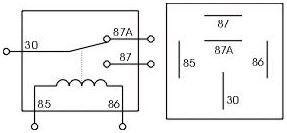
Anyway,.. The relays I bought are the 4 terminal relays.. I don&#39;t have them in front of me,.. but would be terminals 30, 85, 86, and 87.

So essentially 85 is always common (ground).. 30 is going to be what I&#39;ll call my "hot" 12v constant power (I&#39;m sure there&#39;s a better term).. .. 86 I don&#39;t know to be honest, maybe you can explain it a little better.. and 87 is what he called "Always open".. Which basically to me just means it&#39;s what passes the current onward from the terminal 30 ( in this case the 12v power source (from my power wire).

Ground is easy enough.. so 85 no issues with.

Terminal 87 seems easy to understand,.. but he was showing differences in a 5 prong and 4 prong. The 5 had two 87 terminals,.. and my question is based on it&#39;s function which seemed to just send power through both terminals when you switched on the switch.. Is that *any* different than say splicing two accessories that need power together and connecting them to a single 4 post, at terminal 87? I didn&#39;t see any additional purpose for dual 87 posts,.. aside from I suppose if you are trying to limit the amperage.. each terminal 87 would be half amperage of the rated relay.

My relays are 4 prong as I said.. with 30, 85, 86 and 87.. that&#39;s what I needed right? I seem to remember you saying something about getting a 5 pin.. but maybe that was to do with the headunit?

At any rate, could you better explain the function of the 86 terminal?

I know I send the Remote wire to terminal 86,.. then I will splice two wires from terminal 87,.. one to the remote to give the amp&#39;s remote a signal,.. and then one to the fan positive? I&#39;m also, per your instructions, wiring my fused 3amp wire to the fan&#39;s positive (or have I gotten this mixed up now?) -- I have this drawn out on my own diagrams, so I could have made a mistake with two wires going to the fans positive.

Still I&#39;d like terminal&#39;s 30 and 86 explained better in their function. In the diagram it has a coil running from 85 to 86.. So logically I&#39;m not seeing how a coil from the remote wire to ground is going to push power to the amp&#39;s remote from 87 -- Unless the switch in the relay connects , well.. essentially all terminals.

I&#39;ll do some more digging around the net for explanations in the mean time.. I&#39;m sure it&#39;s explained all over,.. I&#39;m really not trying to waste your time here. :) I just like to know how things work even if I already know how to make them work with wiring.

Edit: Watched another video that had the relay open -- Makes it make much more sense:

So have an additional question.

I believe you told me to connect Remote from HU to 86,.. 85 to ground,.. 30 goes to power from amp... and I fuse this connection to the fan positive... and 87 you said to go to the input of remote on amp.. AND to positive on fan.

Two questions.

1) It makes more sense to me to have 87 going to positive on fan .. and that&#39;s the sole lead going to the fans positive. Why do I say this? Well,.. If I&#39;m connecting 30 to the fan positive AND 87 to fan positive.. it sort of makes the relay redundant doesn&#39;t it? Which leads to question two.

2) Why am I using a relay to begin with? It seems to me it&#39;s merely a switch to the fan going on and off.. What&#39;s holding the power down is going to be the 3amp fuse in line going to positive on the fan. The amp already works via the remote wire and clicks when that wire gets power (which sounds like that&#39;s a relay in the amp by the way this all works).. So it&#39;s almost like wiring up this relay serves no purpose because the amp is already switching on and off when I want it to.. Ahh.. as I&#39;m typing I think I get it -- Going from the power off the amp is going to keep the fan on the whole time,.. and the relay is going to keep it on when the remote has power, and off when remote doesn&#39;t have power. -- So this just leaves me with original question one.. If I&#39;m connecting both 87 to Fan terminal AND power from 30 fused to fan terminal,.. is this the right wiring layout, because in that way it doesn&#39;t make the relay make any sense to me --

I see the relay as an "on/off" switch.. and to me it would seem like the fan + terminal should just get a connection from one terminal of the relay, not two. Perhaps you can explain why two (or tell me I&#39;m just mixed up and it is just one terminal going to the fan (+) positive terminal?

I remember the main reason I&#39;m using the relay in the first place is because the remote wire is something like 250mA,.. which is too low to reliably and safely power anything,..

I appreciate the time and help.
 
Last edited by a moderator:
I'll try to explain it in the simplest terms but please don't mistake it as condescension. I may cover something you already understand but that doesn't mean I don't think you know it. ;-)

Relays are electric switches. There is only one fundamental difference between a relay and the light switch in your office and that's the means by which it is moved. The switch in your office is moved by your hand and the switch on a relay is moved by electrical current exiting the coil and creating magnetism that pulls the switch from its normal position. In this case, the coil is pins 85 &amp; 86. Those pins are not polarity conscious, meaning that neither is positive or negative but obviously, one needs a positive connection and the other, a negative, in order for it to work.

Moving on to the switch portion of the relay... the only difference between 4 &amp; 5 pin relays is that 4 pin automotive relays are normally open and 5 pin automotive relays are normally open or normally closed. Normal = the rest position of the switch or, the position it reverts to when the coil is not energized. The 5 pin relays we're discussing designate the N.O. (normally open) terminal as pin 87 and the N.C. (normally closed) terminal as pin 87a. And again, they are not to be confused as being the same. They are opposites and they serve the opposing functions of closing a circuit or opening a circuit, respectively.

For what you're doing, you need pins 30 &amp; 87 (N.O.) and you do not need pin 87a. I mentioned 5 pin relays because they're quite common and obviously for me as a dealer, more versatile as they can serve to switch multiple applications... thereby allowing me to stock fewer parts but still be able to accomplish multiple goals. But for your goal, a 4 or 5 pin relay will work and for the sake of this conversation, forget about pin 87a altogether... you don't need it and it does not exist. :)

Also, to reinforce the explanation, pins 85 &amp; 86 work together and are completely (electrically) isolated from pins 30 &amp; 87. 85 can be ground and 86 can be positive from the head unit or vice versa... it doesn't matter. 30 &amp; 87 are the two connections on a single pole, single throw switch and for your application, it doesn't matter which is used for power and which is used to send that power to the amp and fan. 30 is usually used as the power input but again, it doesn't matter. All that matters is that you have a switch (pins 30 &amp; 87) between the power feed and the devices you wish to send power to.

In summary, the only reason we're even using a relay is so that you can switch high current devices with a low current signal and that's the single most common application for automotive relays. If your head unit provided 1 amp of current to the remote wire, we wouldn't need a relay but since it doesn't and we still need to use the head unit to switch on a higher current circuit, a relay does that while also isolating (protecting) the head unit's remote wire from the high current draw of the amp + the fan.

I hope that makes some sense, lol.

 
@bbeljefe ;
No, thank you! I totally understand it 100% now. I have so many uses for relays now,.. lol. I thank you for imparting this simple information to me,.. I can be dense sometimes.

Anyhow -- What was throwing me off was that I drew my diagram wrong!

I had terminal 30 going to the Amp (battery) AND to the Fan. I ALSO on my diagram had 87 going to the Fan. That&#39;s not right.

30 is going to be my input power.. so that&#39;s going to be fused at 3amps from the amp power wire.. and will NOT go to my fan (directly) as terminal 87 will go to my Fan&#39;s positive + Remote wire to amp.

That makes so much sense.. as the main "power" is sent across 30 to 87 when it switches as the electromagnet in the coil powers up and pulls the switch over connecting the circuit.. I was trying to figure out why (on my diagram) I was putting power from terminal 30 AND 87 to the fans positive.. that wasn&#39;t equating with me.. and it should cause it&#39;s wrong!

Terminal 30 is just giving the relay it&#39;s MAIN 12v power.. And 86 (I know 85 and 86 can be siwtched around.. as can others... ) is the "trigger" to power up the coil.. which will then allow terminal 87 to receive the power from the battery (amp.. but it&#39;s the battery wire).. Which is going to power the fan,.. and is going to send power to the remote wire to the amp.

Soo.. as long as that is right, I&#39;m good on wiring.

But,.. let me ask you this -- Now the remote input on the amp is going to get higher than the 250mA the headunit is putting out.. does that matter at all? (Since the remote from HU is now going to go through this relay, and out terminal 87 which will be feeding more power to the remote in than it was getting.

On that note.. It should also work if I spliced the HU remote wire and had one end going to the amp, and one into this relay at 86. The 87 JUST going to fan, and not to remote in on amp (as the spliced remote would be going into the amp ).

But, you said to run remote to 86,.. and then feed the remote input on amp from 87 -- So it must not make a difference if the Amp&#39;s remote in is receiving 250mA or 3 amps.

Thank you for your patience, and it was far from condescending.. I&#39;m being very dense on this matter, and I apologize.
 
I'm glad that made things more clear for you!

And no, it doesn't matter how much current is available to the amplifier's turn on relay, it will only draw as much as it needs. Likewise with the fan or any other electrical device... the supply doesn't determine how much current a device draws, the device does.

As for the HU remote powering both the amp and the fan relay, it can do that but that would defeat the purpose of the relay, which is to ensure that only a minimum amount of current is drawn from the head unit's turn on circuit. And with that said, I'm kinda surprised that no one has popped in here to argue that they have three amps and two fans running from their head unit's turn on output with no problems, because that's what I usually hear. And the answer to that argument is... YET. In all likelihood you could run both the fan and the amp directly off the head unit's remote but the problem is that if there is a problem, the damage can be irreparable.

Sorry for the tangent but that just came to mind.

 
I'm glad that made things more clear for you!
And no, it doesn't matter how much current is available to the amplifier's turn on relay, it will only draw as much as it needs. Likewise with the fan or any other electrical device... the supply doesn't determine how much current a device draws, the device does.
Thanks,.. and that is what I concluded based on the use.. I'm used to thinking of power in terms of having to attenuate voltage prior to it reaching a device.

As for the HU remote powering both the amp and the fan relay, it can do that but that would defeat the purpose of the relay, which is to ensure that only a minimum amount of current is drawn from the head unit's turn on circuit. And with that said, I'm kinda surprised that no one has popped in here to argue that they have three amps and two fans running from their head unit's turn on output with no problems, because that's what I usually hear. And the answer to that argument is... YET. In all likelihood you could run both the fan and the amp directly off the head unit's remote but the problem is that if there is a problem, the damage can be irreparable.

Sorry for the tangent but that just came to mind.
Well,.. As always it took me longer than expected to finish a project than anticipated,.. I first mocked up the fan with electrical tape and just the fuse on the Pos terminal of the fan and negative ... Positive lead to the amps power wire, and negative to the negative.. Just so I could get an idea of the noise of the larger sized fan I was going to use.. You never know the noise output in different locations as I've only ever used them in computers.

It was a bit louder than I expected, not much.. but given it has to run at full rpm due to now PWM control with a straight current going to it, it's going to be as loud as the fan can possibly be (max rpm all the time). Also I wanted to make sure the fan worked properly and I still hadn't figured out just how I was going to mount it, etc.

I started mocking up a shelf to make use of the rest of the room in that slot,.. and there's just no point in using that slot for anything but the amp,.. even a shelf right over the amp gives about 1-1.5" of space.. not worth further restricting the amp imo.

So the shelving idea went out,.. and then things changed. I just went for the heart of the matter in this,.. If it was going to be the amp only in there, I was going to start fabricating. So I grabbed the dremel and mocked up the fan , checked clearances with the door shut, and then started drilling out holes for air to be ****** through ,.. as I mounted the fan on the *inside* of the door, so it couldn't be seen.. and to pull cabin cool air into the "glovebox/cubby" to get the maximum potential out of this since it's now an Amp slot only. The door was much thicker than other trim pieces I've been fabricating in the car.. so I spent a solid hour getting the holes properly dremeled and buffed out so it wasn't a cut up mess. Than I tested the fan completely flush against the inner door,.. and it was a little louder this way. So I knew it needed just a little bit of spacer between it and the door to quieten it down and pull air better.

I wasn't going to run out for a couple of "spacers" .. so I dug around until I found two double thick washers .. and had to find some screws that were long enough to get through the door, spacers, and into fan holes (standard screws for the fan weren't an option).

Then I went to the process of cutting all the wire, putting spade female connectors on the Fan Positive, Remote wire coming off the relay, Ground coming off relay, and the 30 terminal that was going to the power cable on amp. Got all that together, wire lengths measured out, etc.. Then I had some of those clips where you put over a wire and then run the butt of another wire into and press down and it "splices" into both wires (never used them before). Well had it all hooked up.. and went to test. Amp came on, but fan didn't power up.

I knew it was those crap "easy splice" connectors. I took them off and they didn't pierce the sheathing of the wiring,.. (I was using two,. one on the Remote wire, and one on the ground wire.. ) -- So I Ran an additional wire into the remote wire slot (instead of splicing the remote).. and an both the fan ground and the 85 terminal wire into the amp ground.. Hooked them up,.. and tried again.

Turned on headunit,.. Click, relay -- Fan started,.. then a second later.. click Amp. Relay is considerably quicker than the power on of the amp (by a second or two). But success!

Just to be "safe" I wrapped all four terminals of the relay in electrical tape in case them got move around and touched something else.. you never know. Then I worked the relay and wires out of sight, and on the "power side" of the amp, but underneath it where I have the other wiring "hidden",.. left enough slack for the door to open and nice cool air is being pulled into the slot.

I'll take a picture of it and add it in a bit.. but the fan is one of the best made... But it's Noctua, so it's ugly as sin lol.. So it's not exactly a "show piece".. The holes on the outside aren't as pretty as they could be,.. but that's primarily because I'm going to eventually cut the enter section out and put a Black guard and some dark "mesh" like a filter but that allows air to flow freely; So it will look more "cleaned up" and to get even more airflow in there.

Intake Holes (Not perfection here.. but not finished):


Fan Wired via Relay - mounted on spacers Pulling Cabin Air:


I'm even thinking about grabbing a vent to mock up in the slot, shouldn't be too difficult,.. and maybe putting some smaller vents in other locations on the door to let some air escape if need be.

But for now it's fully functional, and not a "Death Box" as VWBobby calls it. //content.invisioncic.com/y282845/emoticons/smile.gif.1ebc41e1811405b213edfc4622c41e27.gif

Thanks for the help.

 
Activity
No one is currently typing a reply...
Old Thread: Please note, there have been no replies in this thread for over 3 years!
Content in this thread may no longer be relevant.
Perhaps it would be better to start a new thread instead.

Similar threads

  • Locked
I have a zapco 4.0 and 6.0 that was stored in an area near the beach and corroded it pretty bad. Never was powered since it was stored working...
14
4K
Normally I don't cheer players losing...but every since LeBron said he was the greatest ever...well...go nuggets 🤣🤣🤣
1
842
So, I had just picked up a Rockford Fosgate P300-2. A 2-channel amp. I had purchased it for 20$ knowing it wasn't working. But I was hoping it was...
0
972

About this thread

Chromatic

Senior VIP Member
Thread starter
Chromatic
Joined
Location
B'ham, AL
Start date
Participants
Who Replied
Replies
87
Views
6,936
Last reply date
Last reply from
Chromatic
IMG_6578.png

saints747

    May 7, 2024
  • 0
  • 0
IMG_6579.png

saints747

    May 7, 2024
  • 0
  • 0

Latest topics

Top